CONTACTS about STEMET brazing filler metals:
tel-fax: +7 (495) 323-92-68,
address: MIFI-AMETO, Ltd Kashirskoe shosse. 31, 115409 Moscow, Russia
Опубликовано в журнале:
Journal of Nuclear Materials 271-272 (1999) 410-414.
Be-Cu joints based on amorphous alloy brazing for divertor and first wall application
B. Kalin a, V. Fedotov a, 0. Sevryukov a, A. Plyuschev a, I. Mazul b, A. Gervash b, R. Giniatulm b
a
Moscow State Engineering Physics Institute, Kashirskoe sh. 31, Moscow 115409, RFb
D. V. Efremof Institute of Electrophysical Apparatus, St. Petersburg 189631, RFAbstract
The limitation on using silver-based alloys for brazing ITER in-vessel components created a development problem for new brazing materials. An application of Be tiles joined to a Cu-based heat sink will be discussed in this paper. For this purpose, rapidly solidified ribbon-type filler metal STEMET 1108® (Cu-Sn-In-Ni system) with a melting temperature of 750 oC and a thickness up to 50
mm was developed. A new temperature regime and heating method were applied during this brazing procedure. This improves the properties of joints significantly, in comparison with conventional brazing in a resistance furnace. These treatments can increase the operational threshold for Be/Cu joints under cyclic surface heat loading up to 12 MW/m2. Metallographic examinations demonstrated the high quality of brazed joints. The brazed seam has a uniform structure along its entire length. Defects of seam filling, pores, inter-metallic compounds and other inclusions are not seen. The prospects of these joints for fusion reactor applications are discussed. © 1999 Elsevier science B.V. All rights reserved.® STEMET is a trade name of MIFI-AMETO, Ltd.
1. Introduction
Brazing is a process used to join materials by introducing an interfacing metal that has a melting point higher than 450 oС, but lower than melting point of the materials to be brazed [1]. The brazing is the most-used joining technique of ITER materials (CFC- composites, metal-ceramic assembly, SiC-composites, dispersion-strength alloys, beryllium, refractory metals et al.). The most of analyzed references are devoted to join of beryllium: Be-Cu [2-7,17-21], Be-Be [2,8], Be-SS [8], next is joining of Cu: Cu-CFC [9-11], Cu-Cu [7,12,13], Cu-SS [14]. Sometimes, diffusion barriers are used in a brazing process to eliminate the formation of intermetallic between the filler metal (FM) and the base materials and a spacer to regulate difference of thermal expansion coefficient. The general requirements for FMs in brazing of ITER materials must be following:
Selecting FM it is necessary to minimize the high temperature brazing cycle; FM must have narrow melting and solidification ranges. Analysis of references on the brazing technique for ITER materials is shown: as FMs are used Ag-alloys, Cu-alloys, Ni-alloys, elements (Al, Mg, Ti, Si). As this take place, technical solutions is “installating” to commercial FMs. The exeption is investigations of the feasibility of rapidly quenched amorphous FM for ITER materials [6,7,15], but about it will be say below. A new FMs in form of ductile thin foil may be of interest. These foils are manufactured by rapid solidification and they posses some useful properties, for example:
A wetting may be increased by doping of amorphous FMs with active elements: Mn, Ti, Zr, Nb et al. By now it is gained some experience of application of rapidly quenched FMs STEMET for joining of dissimilar PFC-materials: Cu-graphite, Mo-graphite, V-graphite, Be-Cu, V-Be, SS-Be [ 2, 6, 7, 15, 17 ].
The use of thin brazing ribbons allows to save of FMs and to attain acceptable appearance of the brazed joint. For example, the interaction zone of FM STEMET 1108 with beryllium was demonstrated to have a width of no more than 3
mm [15]. This zone was free of large intermetallic grains and cracks. The tensile strength of Cu/Be/Cu brazed joints made by STEMET 1108 was (125 + 12) MPa and the failure of specimens took place in beryllium close to the brazed seam.This paper discusses the problems connected to the brazing of Be with CuCrZr copper alloy using the new ribbon-type rapidly solidified Cu-Sn-In-Ni FM (STEMET 1108) in combination with a fast heating at brazing.
2. Rapidly solidified FM
According to results of previous investigations [15] the work on improvement of rapid solidification process of STEMET 1108® was continued. The main forces were directed on the production of continuous homogeneous ribbon with controlled thickness (50
mm) and minimal thickness deviation (up to 3 mm). For this goal: (i) the micro-doping of alloy by some elements for strengthen and improving of casting properties; (ii) enhanced method of smelting ingots for rapid solidification process; (iii) specially developed regimes for time-heat treatment of melting before rapid solidification process;(iiii) precision control system of dynamic parameters of rapid solidification process were used.The characteristics of rapidly solidified ribbon and cast alloy of STEMET 1108 composition are shown in table 1.
Besides the same FM was presented itself in a good light for brazing of Cu with SS [16]. This fact is demonstrated a possibility of manufacturing of three-metal structure Be-Cu-SS during one brazing cycle.
It is necessary to point the traditional brazing technique of ITER components would be change to increasing of heat and cool rates of brazing assembly. It will be useful for preservation of base material properties (for example, dispersion-strength Cu-alloys).
Table 1
|
Properties |
STEMET 1108 (rapidly solidified ribbon) |
Conventionally cast alloy of STEMET 1108 composition |
|
Chemical composition (wt. %) |
Cu (bal.) - 12 Sn - 9 In - 2 Ni - 1,5 (Mn, Cr, P, Si, Fe) |
|
|
Solidus temperature (° С);Liquidus temperature (° С) |
750 800 |
760 820 |
|
Dimensions of ribbon: thickness (m m); width (mm); length (m) |
50 ± 2 10 ± 1, 20 ± 1 up to 100 |
Bars |
|
Ductility |
Beds 180 ° without fracturing |
Fails in easy bending |
3. Brazing method selection
Metallographic analysis of all previous Be/Cu tested samples [ 21 ] clearly revealed a very thick (~100 m m) brittle intermetallic layer in the bonding seam. We believe that one of the main reason for relatively low number of thermal cycles before failure in preceding testing campaigns is a thick intermetallic formation. It was shown [ 21 ] that all considered previous joining technologies use significantly long brazing (heating-soaking-cooling down) cycle. Such a long cycle takes place because of using the traditional “slow” resistor furnace. At the same time in accordance with practically all references (see for ex. [ 20 ] ) the best results of thermal cyclic testing were achieved when the fast heating like induction furnace was used for brazing. That is why it was decided to use the TSEFEY’s electron-beam heating for the fast brazing procedure.
To provide a relevant ITER cyclic thermal loading the TSEFEY electron-beam facility (St. Petersburg, Russia) was developed. This facility allows to create cyclic heat fluxes with required parameters of a cycle and energy density. The time of a cycle can be varied in the range of 0.1 sec. ... to stationary state. The energy density can be varied in the range 0.1 MW/m2 ... 15 MW/m2. We refer to [ 20 ] for the detailed description and features of the TSEFEY facility, but even from above mentioned parameters it looks suitable for the fast-heating brazing.
A unique brazing process was developed, which uses advanced STEMET 1108 in combination with a fast heating provided by TSEFEY’s electron-beam.
Chemical compositions of used Be (TGP-56) and Cu-alloy (CuCrZr) are shown in table 2. Main physical and mechanical properties of the base alloys are shown in table 3. The CuCrZr properties are strongly dependent on previous heat treatment. In our case the heat treatment was:
Table 2
|
Base metals |
Chemical composition |
|
CuCrZr |
Cu - base |
|
TGP-56 beryllium |
Be(min) - 97.8 |
Table 3
|
Properties |
CuCrZr |
TGP-56 beryllium |
Electrical conductivity |
45 m/W mm2 |
- |
Thermal conductivity |
320 W/mK |
180 W/mK |
Young’s modules |
130 GPa |
297 GPa |
Expansion coefficient |
17.6 10-6/K |
11 10-6/K |
Density |
8.92 g/cm3 |
1.85 g/cm3 |
Ult. tensile strength |
480 MPa |
380 MPa |
0.2% Yield strength |
350 Mpa |
360 MPa |
Total elongation |
18 % |
1,5 % |
Hardness |
140 HB |
- |
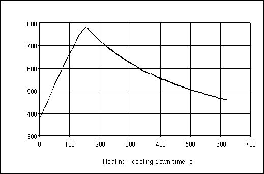
Before brazing the joining surfaces of Be and Cu-alloy were machined and etched. Two Be tiles (40 mm x 40 mm on plane, 10 mm in thickness) were fixed on the CuCrZr surface using light steel clamps. One layer (~ 50 µm thick) of a previously etched STEMET 1108 FM was laid between Be and CuCrZr. These light steel clamps were used mainly for fixing of the Be tiles and the brazing FM on the CuCrZr surface. The pressure for brazing was estimated in the order of 0.1 MPa. Then the assembly was installed into the TSEFEY facility and heated by an electron-beam up to 780° С. The temperature of the brazing zone was controlled with a thermocouple. The heating-cooling down curve for the brazing cycle is presented in fig. 1. The heating rate during the brazing cycle was ~ 160...180 ° С/min., the cooling down rate ~ 20 ° С/min. It is seen that brazing time is significantly less in compare with the brazing-time in resistor furnace.
Fig. 1.
4. Brazing zone microstructure
The microstructure of the brazed joint was investigated using optical microscopy. On the first stage of investigation the Be/CuCrZr joint sample (Sample 1) brazed in a traditional resistor furnace was compared with an identical Be/CuCrZr sample (Sample 2) but brazed using fast electron-beam heating in TSEFEY.
The photos of the brazed seams of samples are given in fig. 2. and fig. 3.
One can see at least two main differences:
After the fast electron-beam brazing in TSEFEY sample 2 was successfully tested during 3 x 10³ cycles under the thermal load ~ 1.5 MW/m2. The brazed seam cross-section of sample 2 after the thermal cycling is presented in fig. 4.
In compare with the initial state (sample 2) the width of brazing seam has been insignificantly increased up to ~ 40 m m but pores or cracks were not found. The recent results of thermal cycling of the joint produced by TSEFEY fast-heating brazing, where the absorbed energy reached the value more than 8 MW/m2, instil confidence [ 22 ].
Conclusion
The main conclusions of this work are:
1. The thick layer of brittle intermetallic compounds formed after Be/Cu joining using 'slow' heating in a resistor furnace is one of the main reasons of failure under cyclic thermal loading.
2. At the expense of reduction of a melting interval and small thickness, the STEMET 1108 rapidly solidified brazing FM permits carrying out the brazing process by fast heating without defects of seam filling and other defects of brazed joints.
3. The combination of fast brazing techniques (like TSEFEY used) with microcrystalline type of brazing alloys reduces significantly the width of the intermetallic zone.
4. Mechanical properties (shear strength) of Be/Cu joints produced by fast heating are significantly higher than heating in a resistor furnace.
5. Fast heating can avoid full annealing of the Cu alloy (in case of using CuCrZr). Recent thermal fatigue results obtained on the TSEFEY facility are evidence of the above mentioned logic.
References
[1] N.J. De Christofaro and A. Datta. Rapidly Quenched Metals 1985, pp. 1715-1721.
[2] B.C. Odegard and B.A. Kalin. J. Nucl. Mater. 233-237 (1996)
[3] T. M. Gurieva and V.T. Pronyakin. J. Nucl. Mater. 233-237 (1996) 918-921.
[4] M. Araki, D.L. Youchison, M. Akiba et al. J. Nucl. Mater. 233-237 (1996) 632-637.
[5] A.A.Gervash, R.N.Giniatouline, I.V.Mazul et al. J. Nucl. Mater. 233-237 (1996) 626-631.
[6] B.A.Kalin, V.T.Fedotov, A.E.Grygoriev et al. Fusion Engineering and Design 28 (1995) 119-124.
[7] B.A. Kalin, V.T. Fedotov, O.N.Sevryukov et al. J.Nucl.Mater. 233-237 (1996) 945-948.
[8] V.R.Barabash, L.S.Gitarsky, G.S.Ignatovskaya et al. J. Nucl. Mater., 212-215 (1994) 1604-1607.
[9] G. Chaumat, P.Le Gallo, G. Le Marois et al. J. Nucl. Mater. 233-237 (1996) 932-934.
[10] P.W. Trester, P.G. Valentine, W.R. Johnson et al. J. Nucl. Mater. 233-237 (1996) 906-912.
[11] R.E. Nygren, C.A. Walker, T.J. Lutz et al. J. Nucl. Mater. 212-215 (1994) 1621-1626.
[12] F. Saint-Antonin, M. Suery, P. Meneses et al. J. Nucl. Mater. 233-237 (1996) 935-939.
[13] S. Chen, J.Y. Liu and B.A. Chin. J. Nucl. Mater. 212-215 (1994) 1600-1603.
[14] S. Chen, T. Bao and B. A. Chin. J. Nucl. Mater. 233-237 (1996) 902-905.
[15] B.A. Kalin, V.T. Fedotov, O.N.Sevryukov et al. Plasma Devices ang Operations, 4 (1996) 245-255.
[17] Yu.G.Prokofiev, V.R.Barabash, V.F.Khorunov et al. J. Nucl. Mater., 191-194 (1992) 483-487.
[18] C.K.Lee, B.A.Chin, S.Zinkle et al. J. Nucl. Mater., 191-194 (1992) 488-492.
[19] E.Franconi, G.S.Ceccotti and L.Magnoni J. Nucl. Mater., 191-194 (1992) 493-498.
[20] V. Gagen-Torn, I. Kirillov, V. Komarov et al. Proc. 18 SOFT, Karlsruhe, (Aug. 1994), pp. 363-366.
[21] A.Gervash, R. Giniatouline, I. Mazul et al. Proc. 2nd IEA International Workshop on Beryllium Technology for Fusion, Wyoming, USA, (Sept. 1995), pp. 364-380.
[22] R. Giniatulin, I. Mazul, V. Komarov et al.Proc. ISFNT-4, Tokyo, (April 1997), Japan.